




Machinist Blueprints
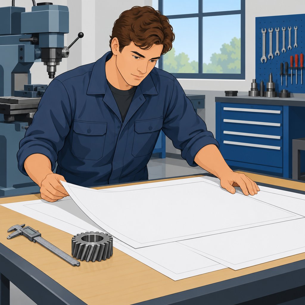
Machinist blueprints guide manufacturing processes.
These detailed drawings specify components, machines, or structures.
They present dimensions, tolerances, materials, and other production requirements.
Blueprints in Manufacturing
Manufacturers use blueprints to produce parts according to exact specifications.
As a result, blueprints support consistency, quality, and accuracy.
They also provide a clear guide for completing manufacturing work.
Reading and Interpreting Design Requirements
Machinists read blueprints to translate design requirements into finished products.
This skill helps them understand geometric relationships, features, and measurements.
Therefore, accurate interpretation connects technical drawings with practical manufacturing tasks.
Accuracy and Attention to Detail
Even a minor blueprint mistake can create significant errors in the final product.
For that reason, machinists must examine every detail carefully.
They also follow instructions precisely to maintain product quality.
Skills and Training for Blueprint Interpretation
Blueprint interpretation requires advanced skills and focused training.
Machinists must understand symbols, lines, geometric dimensioning and tolerancing, and drawing techniques.
With these abilities, machinists can interpret specifications accurately and produce high-quality products.
Understanding Blueprint Symbols and Abbreviations
Blueprint symbols communicate measurements, dimensions, and other information about a part or component.
Machinists use these details to interpret drawings and manufacture accurate parts.
Therefore, recognizing common symbols and abbreviations supports precise blueprint interpretation.
Common Symbols Used in Machinist Blueprints
Blueprints use several line types to communicate important information about part features.
Each symbol helps machinists understand sizes, locations, visibility, or thread specifications.
Consequently, machinists should identify these symbols before determining manufacturing requirements.
- Dimension lines indicate the size or distance of a feature on the blueprint.
- Centerlines show the center of a circular feature or the symmetry of a part.
- Hidden lines represent features that remain invisible from the current viewing angle.
- Thread designations indicate the type and size of threads on a part.
Common Abbreviations Found on Machinist Blueprints
Abbreviations condense frequently used technical terms within blueprint notes and dimensions.
Reading these shortened terms correctly helps machinists interpret specifications efficiently.
In addition, familiar abbreviations reduce confusion when machinists review part requirements.
- OD means outside diameter.
- ID means inside diameter.
- TPR means threads per inch.
- MMC means maximum material condition.
Understanding these abbreviations helps machinists determine precise dimensions and specifications.
Without this knowledge, machinists may struggle to interpret the requirements for a part accurately.
Ultimately, mastering blueprint language helps machinists produce parts that meet specified requirements.
Reading Dimensions and Tolerances
Accurate dimension reading helps machinists interpret part requirements during production.
At the same time, tolerances define acceptable variation during manufacturing.
Together, these details support consistent and functional machined parts.
Representation of Dimensions on Blueprints
Blueprints represent dimensions through numbers, lines, arrows, and other notations.
Linear dimensions identify measurements such as length, width, and height.
Likewise, degree symbols and radius indicators describe angles and curves.
- Blueprints typically show dimensions through numbers, lines, and arrows.
- Linear dimensions commonly display numerical values with corresponding units.
- Angles use degree symbols, while curves use radius indicators.
- Therefore, machinists should check the blueprint scale before interpreting measurements.
- Additionally, dimensions may include tolerances, material specifications, and finishing requirements.
Importance of Tolerances in Manufacturing
Tolerances specify the allowable deviation from a stated dimension.
Consequently, they establish an acceptable range for a part’s size or shape.
Manufacturers use these limits to match design and functional requirements.
- Tolerances help machined parts meet design specifications and functional requirements.
- They can affect a part’s fit, form, function, and interchangeability.
- Manufacturers follow specified tolerances to achieve quality and performance.
- Deviations beyond tolerance limits can cause defects, rework, or product failures.
- As a result, machining processes require careful attention to precision.
By understanding dimensions and tolerances, machinists improve accuracy and consistency.
As a result, they support the quality and functionality of finished work.
Find Out More: Construction Manager's Guide to Risk Management
Interpretation of Geometric Dimensioning and Tolerancing
Geometric dimensioning and tolerancing, or GD&T, uses symbols to communicate design specifications.
Transform Your Career Today
Unlock a personalized career strategy that drives real results. Get tailored advice and a roadmap designed just for you.
Start NowThis language helps machinists interpret blueprint requirements accurately.
Understanding GD&T supports consistent manufacturing and inspection practices.
Common GD&T Elements
Several GD&T elements define important relationships between part features.
These elements establish references, locations, forms, and profiles for inspection.
Machinists use the information to interpret feature requirements on blueprints.
- Feature Control Frames: These frames identify critical features and specify their required tolerances.
- Datums: Datums provide reference points for establishing a coordinate system during measurement and inspection.
- Position: The position requirement locates a feature within a tolerance zone defined by its size.
- Concentricity: This requirement indicates that multiple features must share a common center axis.
- Circularity: Circularity controls the circular form of a feature across a projected cross-section.
- Profile: Profile requirements control a feature’s shape, size, and orientation relative to its true profile.
Importance of GD&T in Manufacturing
GD&T provides clear instructions for producing and inspecting machined parts.
It also communicates design intent through standardized requirements.
Consequently, manufacturers can improve consistency, accuracy, and production efficiency.
- Improved Communication: GD&T standardizes design language and reduces misinterpretation during manufacturing.
- Enhanced Quality Control: GD&T clarifies manufacturing and inspection requirements for machinists.
- Cost Savings: Precise tolerances help minimize scrap, rework, and production delays.
- Interchangeability: GD&T helps parts remain compatible with assembly requirements.
- Design Optimization: GD&T communicates design intent accurately and supports efficient part designs.
Therefore, machinists need a solid understanding of GD&T to interpret blueprints correctly.
Manufacturers that follow GD&T guidelines can support consistent and precise production processes.
Delve into the Subject: Painting Tools 101: Brushes, Rollers, and Sprayers
Identifying Different Views on a Blueprint
Orthographic projections show multiple views of an object from different angles.
These views can include top, front, side, and bottom perspectives.
Each view communicates specific dimensions, features, and shapes.
- Orthographic projections provide accurate two-dimensional representations of a part.
- Each view supplies information about particular dimensions, features, and shapes.
- Machinists use these views to visualize the complete part in three dimensions.
Importance of Three-Dimensional Visualization
Visualizing a part in three dimensions helps machinists understand its complete form.
This understanding clarifies how the part will be manufactured and assembled.
It also helps machinists identify potential issues before machining begins.
- Machinists can better understand a part’s shape, size, and features.
- They can identify potential problems or interferences during the machining process.
- Furthermore, three-dimensional visualization supports clear communication with engineers and other team members.
Explore Further: How to Start a Career as a Roofer: Step-by-Step Guide
Understanding Different Types of Blueprints
Machinists use blueprints as roadmaps for creating precise and accurate parts.
Each blueprint type presents information for a different manufacturing or assembly task.
Therefore, machinists must recognize each drawing’s purpose before beginning work.
Assembly Drawings
Assembly drawings show how multiple components fit together into a finished product.
They display relationships between parts, including their orientations and positions.
Machinists review part numbers, dimensions, and instructions to support proper assembly.
Detail Drawings
Detail drawings describe individual components with precise measurements and manufacturing requirements.
They commonly include tolerances, surface finishes, threads, and geometric requirements.
Machinists follow these details to produce compatible parts that meet specifications.
Schematic Diagrams
Schematic diagrams simplify complex systems by using symbols and connecting lines.
Electrical and hydraulic diagrams use schematics to show current or fluid flow.
Machinists interpret these diagrams to troubleshoot systems and understand component relationships.
The Importance of Differentiating Blueprint Types
Recognizing blueprint types helps machinists select the correct information for each task.
This skill improves accuracy, efficiency, communication, and adherence to project requirements.
Additionally, correct blueprint selection reduces errors, rework, and production delays.
- Enhances efficiency and accuracy during machining processes
- Clarifies project requirements and production specifications
- Prevents errors by directing machinists toward the correct drawing
- Supports communication among team members and stakeholders
Each blueprint type serves a distinct purpose and supplies different production details.
By reading the appropriate drawing, machinists can align their work with project goals.
Using the wrong blueprint may create defective parts, unsafe assemblies, or unnecessary rework.
Clear blueprint selection also helps machinists explain plans, progress, and challenges.
Ultimately, blueprint differentiation strengthens machining accuracy and supports successful project execution.
Explore Further: Choosing the Right Tools for Power Line Work
Software Tools for Blueprint Interpretation
Software tools improve accuracy and efficiency when machinists read and interpret blueprints.
Transform Your Career Today
Unlock a personalized career strategy that drives real results. Get tailored advice and a roadmap designed just for you.
Start NowCAD programs provide digital platforms for viewing intricate details, dimensions, and geometries of machined parts.
Furthermore, digital tools help machinists analyze drawings, collaborate with teams, and streamline interpretation tasks.
CAD Programs for Viewing and Analyzing Blueprints
Programs such as AutoCAD and SolidWorks support blueprint creation, editing, and analysis within manufacturing environments.
These programs allow machinists to examine drawing details and study part geometries digitally.
Additionally, virtual tools simplify measurement, annotation, rotation, simulation, and team collaboration.
- AutoCAD and SolidWorks help manufacturers create, edit, and analyze blueprints.
- Digital platforms display intricate details, dimensions, and geometries of machined parts.
- Machinists can zoom into blueprint areas, add annotations, and collaborate with team members.
- Virtual environments support part rotation, measurement, and machining simulations.
Technological Advancements in Blueprint Interpretation
CAD technology continues to evolve through new features and improved blueprint interpretation capabilities.
Staying informed about current software helps machinists improve efficiency, reduce errors, and meet project deadlines.
Regular training enables machinists to use digital platforms more effectively during blueprint interpretation.
- New CAD features enhance the overall blueprint interpretation experience.
- Updated software helps machinists work efficiently and reduce errors.
- Advanced tools support stress simulations and tolerance checks with greater precision.
- Training and upskilling help machinists use digital platforms effectively.
By using software tools and learning current technologies, machinists can streamline workflows and increase productivity.
These practices also help machinists deliver high-quality machined parts to customers.
Practicing Blueprint Reading Skills
Machinists and manufacturing professionals need strong blueprint reading skills.
Regular practice improves accuracy and efficiency when professionals interpret blueprints.
Proficient blueprint reading can reduce errors during manufacturing processes.
Stronger interpretation skills can increase productivity and work quality.
Benefits of Regular Interpretation Practice
- Regular practice improves accuracy and efficiency when professionals interpret blueprints.
- Proficient blueprint reading can reduce errors during manufacturing processes.
- Stronger interpretation skills can increase productivity and work quality.
- Frequent practice familiarizes professionals with blueprint symbols, lines, and notations.
Resources for Developing Blueprint Reading Skills
- Blueprint reading courses or training programs can teach the fundamentals of interpretation.
- Measuring blueprint dimensions with a ruler or calipers can improve scale understanding.
- Interpreting geometric tolerancing and surface finishes can strengthen technical skills.
- Studying orthographic, isometric, and sectional views can broaden blueprint knowledge.
Dedicated practice helps professionals interpret blueprints accurately and efficiently.
Blueprint reading remains an important skill in the manufacturing industry.
Strong interpretation skills can distinguish skilled and competent professionals.
Applying Blueprint Reading Skills in Machining
Strong blueprint reading skills support success in the machining industry.
Machinists should examine details carefully, select appropriate tools, and practice regularly to improve accuracy.
Consequently, accurate interpretations help machinists prevent errors, save time, and produce consistently high-quality products.
Moreover, continued practice can increase efficiency and strengthen job performance.
Machinists should seek feedback from experienced professionals and continue learning as the industry changes.
Additional Resources
Bing search results for How to Read and Interpret Machinist Blueprints Construction and Manual Labor


